
I went through your suggestions for the rim model and fixed all the errors in TruPLAN. But when I wanted to compute the model in TruFIBER I faced with other errors:
I went through your suggestions for the rim model and fixed all the errors in TruPLAN. But when I wanted to compute the model in TruFIBER I faced with other errors:
1) Error 1 (attached): when I select just ply
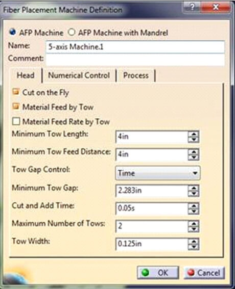
I should mention that I have checked both 1 & 2 as the maximum number of tows and changed the tow width from 6.35 to 3.175 but I faced with the same error. The material for this model is carbon 0.25 inch.
2) Error 2 (attached) : when I select two plies (1 & 2).
Should I select two different reference point in TruPLAN for each plies?
3) We have same problem with the disc model.
As we are going to use thermoplastic head, I was wondering to know that whether the setting for the compressible roller 2 is correct or not? I also have attached some of my settings in TruFIBER.
The first error is because of the settings you have inside of the third slide. You should be setting the tow width parameter to 3.175mm. This parameter should match the Fabric Width set inside of the composites parameters for TruPlan. The compressible roller length is correctly set to 6.35mm. The maximum and minimum number of tows (in this case) should be set to 2. This is because we do not want to compute paths with less than two tows or the posted output will not work correctly.
The second error is because the two plies you have selected for the fiber placement operation overlap each other. You can only add multiple plies to a fiber placement operation if their ply boundaries do not overlap and they are the same orientation. You should create individual fiber placement operations to compute these plies separately.
4) Disk:
In the TruPlan 15 plies of uni-directional tape, [0⁰, 45⁰, -45⁰]5B , under one ply group is generated.
In the TruFiber, all of these 15 plies have been selected for fiber placement operation and the tool path for all of them is successfully computed.
I’m glad you were successful in programming this disk model. I always like pictures if you’ve been able to make the part.
5) Rim:
In the TruPlan 15 plies of uni-directional tape, [0⁰, 45⁰, -45⁰]5B , under one ply group is generated.
- In the first ply (0⁰), as shown in Figure 1, there is an overlap/gap between the start and the end of lay-up course.
By increasing the number of stacked plies, especially when the orientation of tape changes to 45⁰ /-45⁰ the area of this region increases, Figure 2, which leads to non-uniformity of the laminate thickness.
So, I was wondering to know that is there any way to fix this issue?
In the TruFiber, all of these 15 plies have been selected for fiber placement operation but I could compute the tool path only for the first ply (0⁰). I tried to add multiple plies to a fiber placement operation and also create individual fiber placement operations to compute the other plies (2-15) separately but I faced with the same error (please see the screen shot of the error, Figure 3).
- What is your recommendation to fix this error? Is it due to complexity of rim?
I have attached the .CATPart & .CATProcess format of the disk & rim for your consideration. However, due to the size of Disk model (.CATProcess format) it will send in a separate email.
- Is it necessary to add a head model in NC resources for collision detection? or just set its geometry in Fibre placement operation? Because we only have the model for thermoset head (4 tow head)
- As we are going to use thermoplastic head, I was wondering to know that whether the setting for the compressible roller (Figure 4) is correct or not?
You are using an offset method for all of the plies in this model. The pros to the offset method are that you have no gaps and overlaps between courses. The cons are the deviation from the rosette you may get from surface complexity (as you’ve seen on this part). You have a few things you can try to resolve this problem. Switch the propagation mode to Constant Angle instead of Constant Angle Offset. This will maintain the rosette orientation along the surface that you are looking for. However, it will leave you with overlaps of material between courses to compensate. Another option would be to use the guide curve offset method and specify the curve you want the courses to follow. With this process, you may be able to define a curve that gives a better result than the constant angle offset. You can also try different seed points to start with to see if that effects the propagation of courses.
I didn’t have the same results as you when I ran TruFiber. However, the results I got with constant angle offset were not good. We will look at that internally. I did have success with constant angle on the first three plies. I think it should compute the rest of the plies with constant angle as well.
I would recommend creating a model for the thermoplastic head. We really measure the point cloud (collision points) versus the manufacturing surface so you can measure critical areas on the head and create those points in a model to avoid collisions with to make things easier.
The compaction distance would be very small (zero) for the thermoplastic head because it is a steel roller. The compaction roller settings for this head aren’t very important because it will never be able to drop a tow. You will still want to enable the compaction modeling though for better machine normal vector calculations.
6) I went through your suggestions, by changing the propagation mode to Constant Angle angle the problems in Truplan is solved but still I cannot compute the tool paths in TruFibre.
You mentioned that you have successfully computed the tool path for the first three plies. I was wondering if you send that model to me to find where I did wrong.
Can you remind me what version of CATIA you are using again? I don’t want to send you a file you cannot open.
I do not have R2012 installed right now, so I just added the parameters I used here.
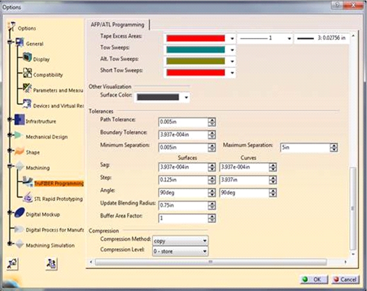
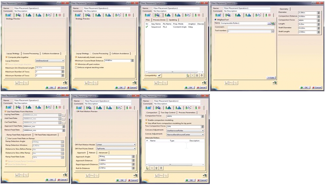
- The compaction values for the roller should be known from the manufacturer. The compressibility is defined as the deformity of the shape based on a known force. For example, I may know a certain roller compresses (deforms) 1.2 inches when a 400 N force is applied. These values are defined in the “Geometry” tab of the roller in the roller definition. These values will be different depending on the roller. A steel roller does not deform or has very little compressibility under high forces. This is why the thermoplastic head should have a low value.
- The shaft parameters are for the shaft that passes through the roller. These values are not as important as the others, but should have values that make sense.
- Using two tows on the thermoset head should be programmed normally. Each tow should have the correct tow width of 6.35 mm.
7) I was wondering to ask you about the extension of files created using majestic (TruFiber) to transfer to the robot.
I finalized my model in majestic and going to make it using robot. Could you please let me know in which format I should save the files to be able to run it with the robot.
To run a TruFiber program on the robot, you need to export a .aptsource file from TruFiber. Once you have that file, you need to post process the .aptsource file to get .knt and .kntpnt file that will run on the robot. It should be wired on the computer to right-click and select/open with Create4TowUNSW or Create1TowUNSW depending on the head you intend to use.
8) Do you know how can I record/save video from the simulation of tape placement in TruFiber?
I’m am not aware of a way to save this replay. You can try to use a screen capture software to record your screen while it plays. This replay is a CATIA function and not a full simulation of the machine.